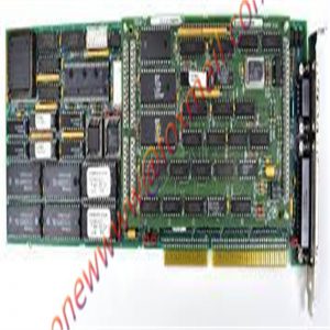
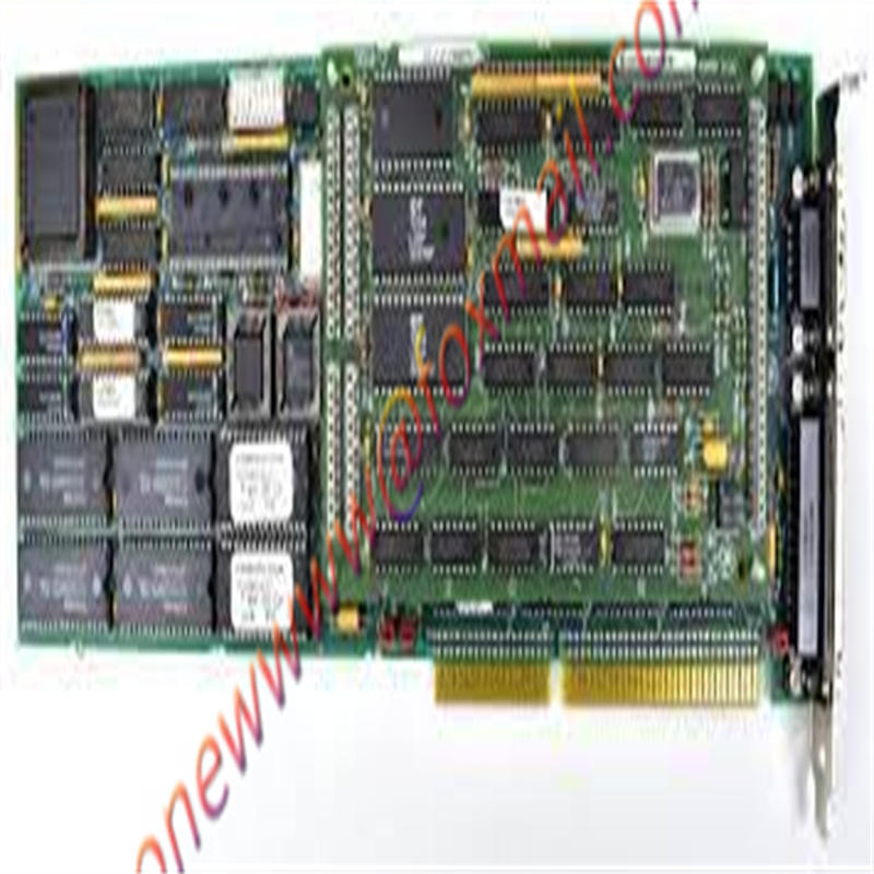
GE DS6800CCIE1F1D DCS industrial control spare parts in stock
Technical data of product parameters
Software Trigger – This mode is selected by clearing both trigger mode control bits in
the CSR. With both bits cleared, a write command to the Software Trigger Command
register located at relative address $000E causes the selected scan mode to begin.
External Trigger – This mode is selected by clearing trigger mode bit 13 and setting
trigger mode bitDS6800CCIE1F1D This enables the board to accept an external trigger. Upon
receiving the external trigger, the selected scan mode is initiated.
Interval Timer Trigger – This mode is selected by setting bit 13
This setting enables the interval timer and the selected scan mode is initiated each
time the timer programmed time interval expires.
Scan Modes
• Random Access
Autoscan – Selected by clearing both scan mode control bits in the CCR and is the
default selection after a reset operation. All active channels are scanned continuously
in this mode.
Single Scan – Selected by clearing scan mode control bit 7 and setting bit 6. All active
channels are scanned through once, and the scan process is stopped until the next
trigger event.
Random Access – Selected by setting bit 7 and letting bit 6 be a Don’t Care. In this
mode, a channel is selected by entering the channel number in bits D05-D00 in the
CCR. This desired channel is sampled, digitized and stored at RAM offset address
$0080.Analog inputs from connectors P3 and P4 are routed through low pass Input Filters
and OP AMP Buffers to the input multiplexers shown in Figure
Channels 00 to 31 are connected through P4 and Channels 32 to 63 are connected
through P3. To provide at least one ground in each of the input connectors, the LOW
inputs for Channels 31 and 63 can be jumpered individually to AGND, or can be left
ungrounded (see the “Configuration and Installation” section of this Manual).DS6800CCIE1F1D is
the internal analog ground. The center row (B row) pins on connectors P3 and P4 are
tied to AGND. This provides a return for all channels if 96-wire ribbon cables are usedDS6800CCIE1F1D
for the analog inputs.
The Analog Multiplexers route one of each group of eight channels to the
Programmable Gain AmplifierDS6800CCIE1F1D multiplexers, which in turn selects an input to
route to the PGA. Input address lines A0 and A1 control the input multiplexer, while
A3, A4, and A5 select the PGA multiplexer input. Each input multiplexer has an
individual enable signal which enables the multiplexer with the desired channel.
Crosstalk and source impedance errors are minimized by the input OP AMP Buffers.
The buffers provide a constant low impedance to the multiplexer inputs. Each channel
contains a buffer on each input line.DS6800CCIE1F1D
Product picture display

I guess you want to know
What if there is a quality problem?
Seven-day acceptance period, one-year warranty period
When can we deliver it?1-3 working days
How about the quality?New or second-hand
How to get the quotation?Phone, WeChat, email and whatApp can all be used
Email: onewwww@foxmail.com
About us service idea:
The company takes production suspension control system parts and components as its dominant products
As long as it is what you want, I can help you find it! Good price! Our purpose:
Build customer relationship with sincerity
Obtain customer satisfaction through service
Win the trust of customers with products
Improve work efficiency with actions
Please contact us for the products you need urgently
You can’t find the product. Please contact us
Products you can’t buy. Please contact us
reminder
For more products, please contact the email for inquiry onewwww@foxmail.com
This article from the temporal Ming sheng automation equipment co., LTD.,
link: http:www.onewwww.com


Reviews
There are no reviews yet.